Tinker Thoughts Blog
Welcome to the Tinker Thoughts Blog — hands-on projects, practical tutorials, and insightful tips in the maker and electronics space. We dive into a wide range of topics including Internet of Things (IoT), electronics troubleshooting, home automation, rapid prototyping, and RF communication. You’ll also find detailed guides on 3D printing custom enclosures and PCB mounts, as well as experiments in electrical circuits, embedded systems, and other DIY innovations. Whether you're a hobbyist, engineer, or curious tinkerer, you'll find inspiration and technical depth here.

TTB #35: How to Break Female Header Pins
Learn the easiest way to break female header pins. This guide shows a simple technique that involves removing one sacrificial pin, cutting the plastic housing, and sanding the end for a clean finish. The method works with standard 2.54 mm female headers commonly used with Arduino, ESP32, Raspberry Pi, breadboards, and custom PCBs. Follow the step by step instructions and avoid the common mistake of cutting the wrong position by remembering to count one extra pin before you begin.

TTB #34: Arduino Nano 3.3V Pin Current Limit: How Many mA Can It Supply?
How much current can the 3.3 V pin on an Arduino Nano actually supply? The answer depends on the board design, not just the microcontroller. In this article, we explain why the classic Arduino Nano is limited to 50 mA, how it generates its 3.3 V supply using the FT232RL USB interface IC, and why some Nano compatible boards provide significantly more current. We also compare the Arduino Nano with the PTSolns Nano Flip, which features a dedicated 3.3 V regulator rated for 160 mA, helping you choose the right board for your project's power requirements.

TTB #33: Introducing the I2Connect Family of I2C Modules
Discover the new PTSolns I2Connect Series, a growing family of plug and play I2C expansion modules designed for rapid embedded development. Built around Qwiic compatible connectors and fully compatible with STEMMA QT, every module supports both 3.3 V and 5 V systems while sharing a consistent form factor for easy integration. The first three releases include the AHT20 Temperature & Humidity sensor, VEML7700 Ambient Light sensor, and 2 Mbit EEPROM memory module. Each includes a dedicated open source library that installs directly from the PTSolns IDE or Arduino IDE Library Manager, helping you get started in minutes.

TTB #32: We Launched a Reddit Sub r/PTSolns
We're excited to announce the launch of the official PTSolns Reddit community, r/PTSolns. Created for makers, students, educators, and engineers, this new community is a place to ask questions, share projects, exchange ideas, and get support using PTSolns products. Whether you're programming one of our microcontroller development boards, experimenting with an I2Connect module, or building your latest embedded project, everyone is welcome. We hope this becomes a friendly space where the community can learn from one another, inspire new ideas, and help shape future PTSolns products. Join us and become part of the conversation today!

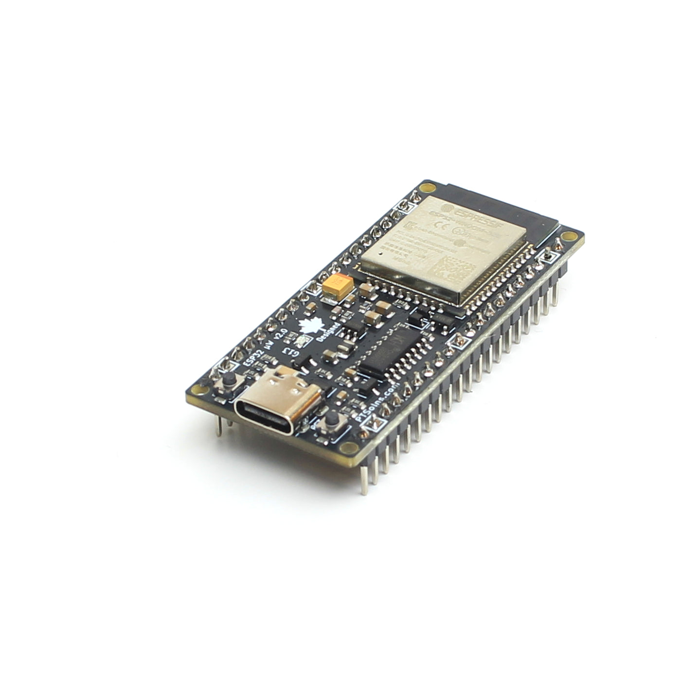
TTB #31: How to Select the Right Microcontroller
Choosing the right microcontroller isn't about buying the fastest or most expensive option. It's about selecting a platform that meets your project's requirements while remaining easy to develop with. In this guide, I share the process I use when designing real embedded systems, from evaluating peripherals and voltage compatibility to considering documentation, development tools, and long term availability. You'll also find practical examples from my own projects, common mistakes to avoid, and recommendations for beginners and experienced makers alike. Whether you're building an IoT device, robot, drone, or home automation project, this guide will help you choose confidently.

TTB #30: This is Why We Do QC
Ever wonder what goes into manufacturing a reliable microcontroller? Inside the PTSolns workshop, quality control (QC) is everything. In this post, we take you behind the scenes of our Thorough hardware testing procedure for the Nano Flip 3V3 fresh off the production line. Discover our multi-step electronics inspection process, from burning the custom ATmega328P bootloader and flashing firmware sketches to catching physical PCB manufacturing defects. Learn how we track failure rates, optimize circuit board performance, and handle defective hardware to ensure every microcontroller we package delivers top-tier reliability for your electronics projects.