

Product Description
This ultrasonic sensor is the latest version of the popular HC-SR04 package. Previous versions are outdated and not nearly as flexible as this one. What's different with this latest version? For starters, the accepted input voltage ranges from 2.8V to 5.5V. This is convenient if you want to power the sensor with a microcontroller as it will work with either a 3.3V microcontroller or a 5V microcontroller.
Unlike the previous ultrasonic sensors, which can only communicate with the microcontroller using the general purpose input/output (GPIO), this new 2021 version can communicate via four different methods:
Mode 1: GPIO
Mode 2: I2C (NEW FEATURE)
Mode 3: 1-Wire (NEW FEATURE)
Mode 4: UART (NEW FEATURE)
The default mode is Mode 1, which is the original communication method for this device using the GPIO pins. In order to select one of the other communication modes, the user must set the corresponding M1 and M2 jumpers on the back of the component, as shown below:

Ultrasonic Sensor 2021 Version
Tutorial for Mode 1: GPIO Method
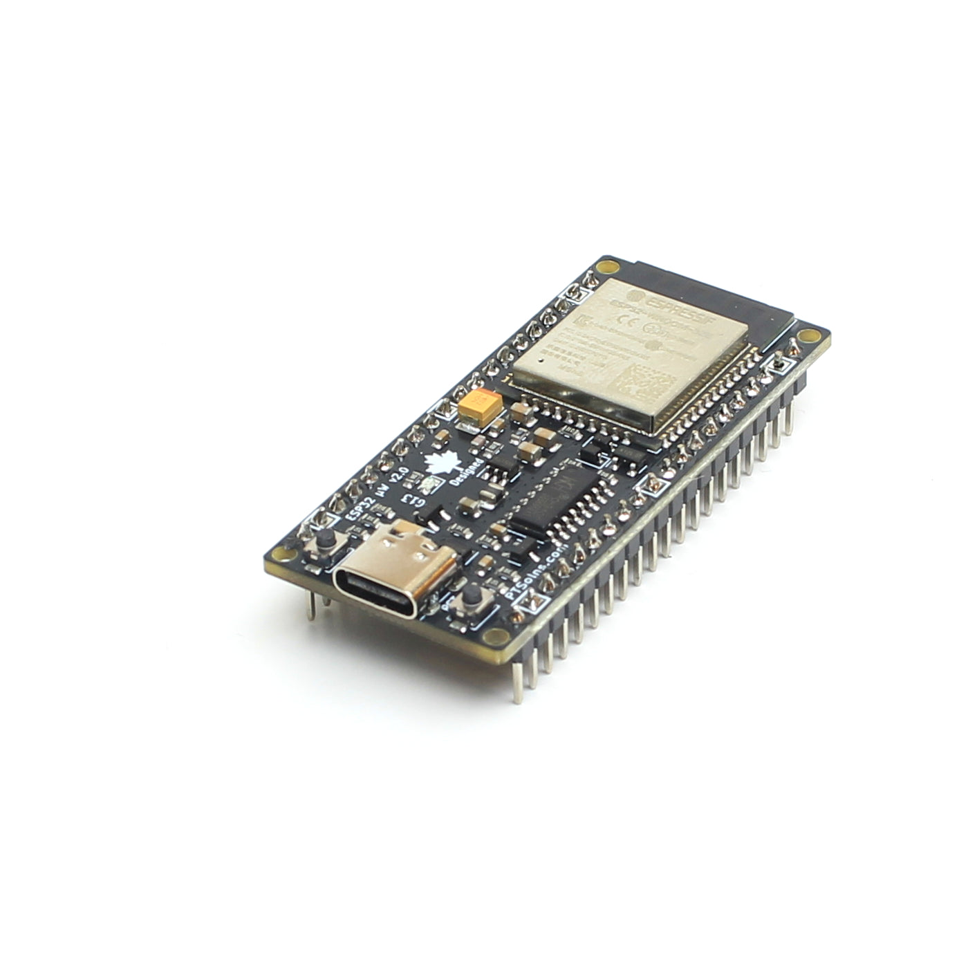
For this Mode 1: GPIO Method simply connect Ground GND and VCC to the power pins of the Dev Board (Uno R3+, Nano Flip, ESP32 microWatt, Nano Flip 3V3, etc). Connect the TRIG pin to Pin 7, and ECHO pin to Pin 6.
// Project title: "Tutorial: Ultrasonic Sensor (Mode 1: GPIO Method)"
// Date of last edit: Dec 4 2021, PTSolns
// Overview: This is the script for interfacing the ultrasonic sensor (version 2021) in Mode 1 (GPIO)


// Set trigger and echo pins
const int trig_pin = 7;
const int echo_pin = 6;


void setup() {
   Serial.begin(9600); // Starting Serial Terminal
}


void loop() {
   long duration, inches, cm;
   pinMode(trig_pin, OUTPUT);
   digitalWrite(trig_pin, LOW);
   delayMicroseconds(2);
   digitalWrite(trig_pin, HIGH);
   delayMicroseconds(10);               // The HC-SR04 ultrasonic sensor requires only a 10us trigger pulse. This actives the module to send 8 pulses at 40kHz.
   digitalWrite(trig_pin, LOW);
   pinMode(echo_pin, INPUT);            // Listen to the echo pin.
   duration = pulseIn(echo_pin, HIGH);  // The duration is the time between the sending of the 8 pulses and the return of the 8 pulses.

   // Convert duration to distance (inches and cm)
   inches = duration / 74.0 / 2.0;
   cm     = duration / 29.0 / 2.0;

   // Print results to monitor
   Serial.print(inches);
   Serial.print("in, ");
   Serial.print(cm);
   Serial.print("cm");
   Serial.println();
   delay(100);
}
Tutorial for Mode 2: IIC (I2C) Method
For this Mode 2: I2C Method simply connect Ground GND and VCC to the power pins of the Dev Board (Uno R3, Nano Flip, ESP32 microWatt, Nano Flip 3V3, etc). If using an ATmega328P based microcontroller, for example, connect the SCL pin to A5, and SDA pin to A4.
// Example: Mode 2) I2C (M1=1, M2=0)
// Last Update: Sept 16, 2025
//
// CONNECTIONS
// In this example we are using the 5V ATmega328P based Uno R3+ microcontroller development board.
// But all other common dev boards should work
// HC-SR04 -> Uno R3+
// VCC -> 5V
// GND -> GND
// SDA -> A4
// SCL -> A5

// OPERATIONAL NOTES
/*
This ultrasonic module is designed for general distance measurement and typically provide a measurable range of about:
Minimum range: ≈ 2 cm (limited by transmit/receive dead zone)
Maximum range: ≈ 450 to 500 cm (4.5 to 5 meters) under ideal conditions

Key points
- Accuracy is best from 5 cm to 300 cm
- Beyond ~3 m, readings become more sensitive to target size, angle, and ambient noise
- Objects must be flat, hard, and perpendicular to the sensor to reflect the ultrasonic pulse effectively
*/

/*
The ultrasonic module integrates a dedicated controller (RCWL-9191/9300C/9200 series) that implements a proprietary I²C communication protocol, distinct from the commonly referenced SRF02 protocol.
In this protocol, the device operates at the fixed I²C address 0x57.
To initiate a ranging operation, the host transmits a single command byte 0x01 to this address.
After a measurement delay of approximately 100–150 ms, the host reads three consecutive bytes from register 0xAF.
These bytes represent the measured distance in micrometers.
The combined 24-bit value must be divided by 1000 to obtain the result in millimeters, and can be further divided by 10 to express the result in centimeters.
*/

#include

const uint8_t I2C_ADDR = 0x57;          // Device address
const uint8_t CMD_START = 0x01;         // start ranging
const uint8_t REG_READ  = 0xAF;         // returns H M L
const uint16_t MEASURE_DELAY_MS = 120;
const uint16_t PERIOD_MS = 300;

void setup() {
  Serial.begin(9600);
  Wire.begin();
}

void loop() {
  Wire.beginTransmission(I2C_ADDR);
  Wire.write(CMD_START);
  uint8_t err = Wire.endTransmission();
  if (err) {
    Serial.print("I2C err "); Serial.println(err);
    delay(PERIOD_MS);
    return;
  }

  delay(MEASURE_DELAY_MS);

  Wire.beginTransmission(I2C_ADDR);
  Wire.write(REG_READ);
  Wire.endTransmission(false);
  Wire.requestFrom((int)I2C_ADDR, 3);

if (Wire.available() == 3) {
  uint32_t H = Wire.read();
  uint32_t M = Wire.read();
  uint32_t L = Wire.read();
  uint32_t micrometers = (H << 16) | (M << 8) | L;
  float cm = micrometers / 10000.0f;  // convert µm → cm
  Serial.print(cm, 2);
  Serial.println(" cm");
} else {
  Serial.println("no data");
}

  delay(PERIOD_MS);
}
Technical Specifications
- Operating voltage: 2.8V to 5.5V
- Measuring distance: 2cm to 400cm
- Measuring angle: 15 degrees
- Current consumption: 2mA (with VCC=3.0V)
- NOTE: Our experiments show the following current consumption. 2mA @Vcc=3.0V, 2.3mA @ VCC=3.3V, 3.6mA @ VCC=5.0V.
- Operating frequency: 40kHz
- Weight: 7.4g
- PCB dimensions: 4.5cm X 2.0cm
- Thickness: 1.5cm (not considering connecting header pins)
- Mounting holes: 4 (grounded), 4.2cm X 1.7cm, 2mm diameter


