

ADS1115 4-Ch 16-Bit ADC via I2C
ADS1115 4-Ch 16-Bit ADC via I2C
Couldn't load pickup availability
NOTE: For large quantity orders with custom pricing please contact us directly.
About this item
- 16-bit ADC with Programmable Gain: The ADS1115 is a precision, low-power, 16-bit analog-to-digital converter (ADC) with an internal programmable gain amplifier (PGA), allowing input ranges from ±0.256 V to ±6.144 V, ideal for small sensor signals and higher voltage sources alike.
- 4-Channel Input with I²C Interface: It features four single-ended inputs or two differential inputs selectable via software, and communicates using the I²C protocol with adjustable data rates up to 860 samples per second (SPS).
- Internal Voltage Reference and Comparator: The ADS1115 includes an internal voltage reference and a built-in comparator for simple threshold-based triggering, making it suitable for power-constrained or embedded applications needing signal monitoring without continuous MCU attention.
- Wide Voltage and Logic Compatibility: Operates from 2.0 V to 5.5 V supply voltage, making it compatible with both 3.3 V and 5 V microcontrollers. Logic levels on SDA/SCL match VDD, and the input voltage on analog channels must remain within VDD + 0.3 V and GND – 0.3 V for safe operation.
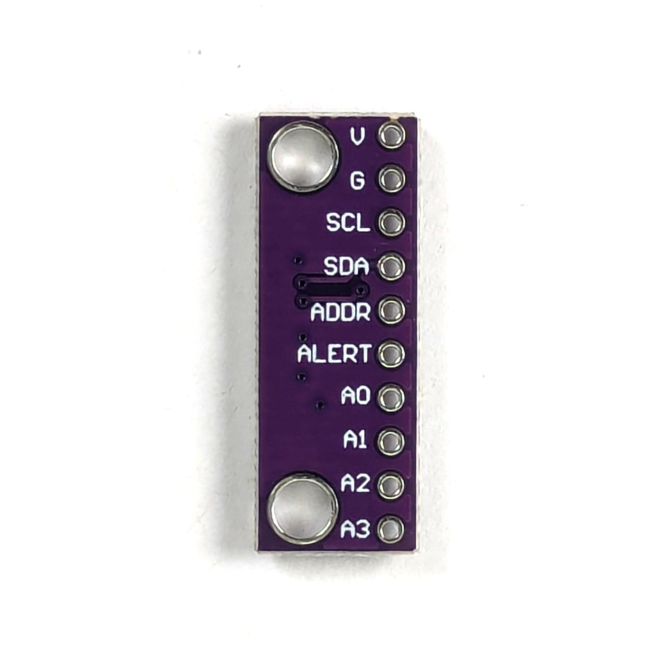
- Configurable I²C Address via ADDR Pin: The ADS1115’s I²C address can be changed by wiring the ADDR pin to one of four options—GND (0x48), VDD (0x49), SDA (0x4A), or SCL (0x4B)—allowing up to four devices to share the same I²C bus without address conflicts.
- Programmable Alert Pin (Comparator Output): The ADS1115 features an open-drain alert pin that triggers when the input voltage crosses user-defined threshold levels, enabling real-time monitoring and interrupt-driven responses without continuous polling.
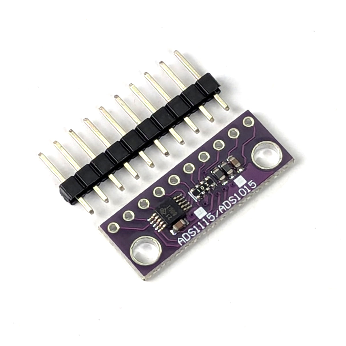
- What’s Included: Each package includes one (1) ADS1115 module, one (1) set of make headers. This is a kit, SOLDERING REQUIRED.
-
PTSolns Customer Support & Resources: We’re here to help. Contact PTSolns support for assistance or technical questions.
Product Description
The ADS1115 is a high-resolution, low-power analog-to-digital converter (ADC) module ideal for applications requiring precision analog measurement. With its 16-bit resolution and integrated programmable gain amplifier (PGA), the ADS1115 can accurately measure small differential voltages and larger single-ended signals, making it versatile for a wide range of sensor interfaces such as thermocouples, strain gauges, and analog potentiometers.
This module supports four analog input channels, configurable as four single-ended inputs or two differential pairs. The onboard PGA allows input voltage ranges from ±0.256 V to ±6.144 V, helping users match the input range to the sensor output for optimal resolution. Sampling rates are selectable via software, with speeds up to 860 samples per second, balancing precision and power consumption depending on the application needs.
The I²C interface ensures easy connectivity with microcontrollers, supporting multiple I²C addresses for simultaneous use of more than one ADC module. Additionally, the ADS1115 includes a built-in comparator, enabling signal threshold monitoring without requiring constant microcontroller polling—perfect for low-power systems or event-driven designs.
What does 16-bit resolution mean?
When we say an ADC (Analog-to-Digital Converter) has “x-bit resolution”, it means the ADC can represent an analog voltage as one of discrete digital values. For example, a 16-bit ADC can produce different output levels. This is like dividing the input voltage range into 65,536 tiny steps or slices.
To understand this better, imagine you have a measuring ruler divided into many small marks. The more marks on the ruler, the more precisely you can measure something. In the case of the ADS1115, the “ruler” is the voltage range it can measure, and the “marks” are the digital values it can output.
If the ADC’s input range is, say, 0 to 5 volts, and it has 16-bit resolution, it means it can detect voltage changes as small as:
This tiny step size means the ADC can distinguish very small differences in voltage. By comparison, an 8-bit ADC only divides the range into 256 steps, which means each step would be about 0.02 V (20 mV), much less precise.
So, the higher the bit resolution, the smaller the voltage changes the ADC can detect, and the more accurate your digital representation of the analog signal will be.
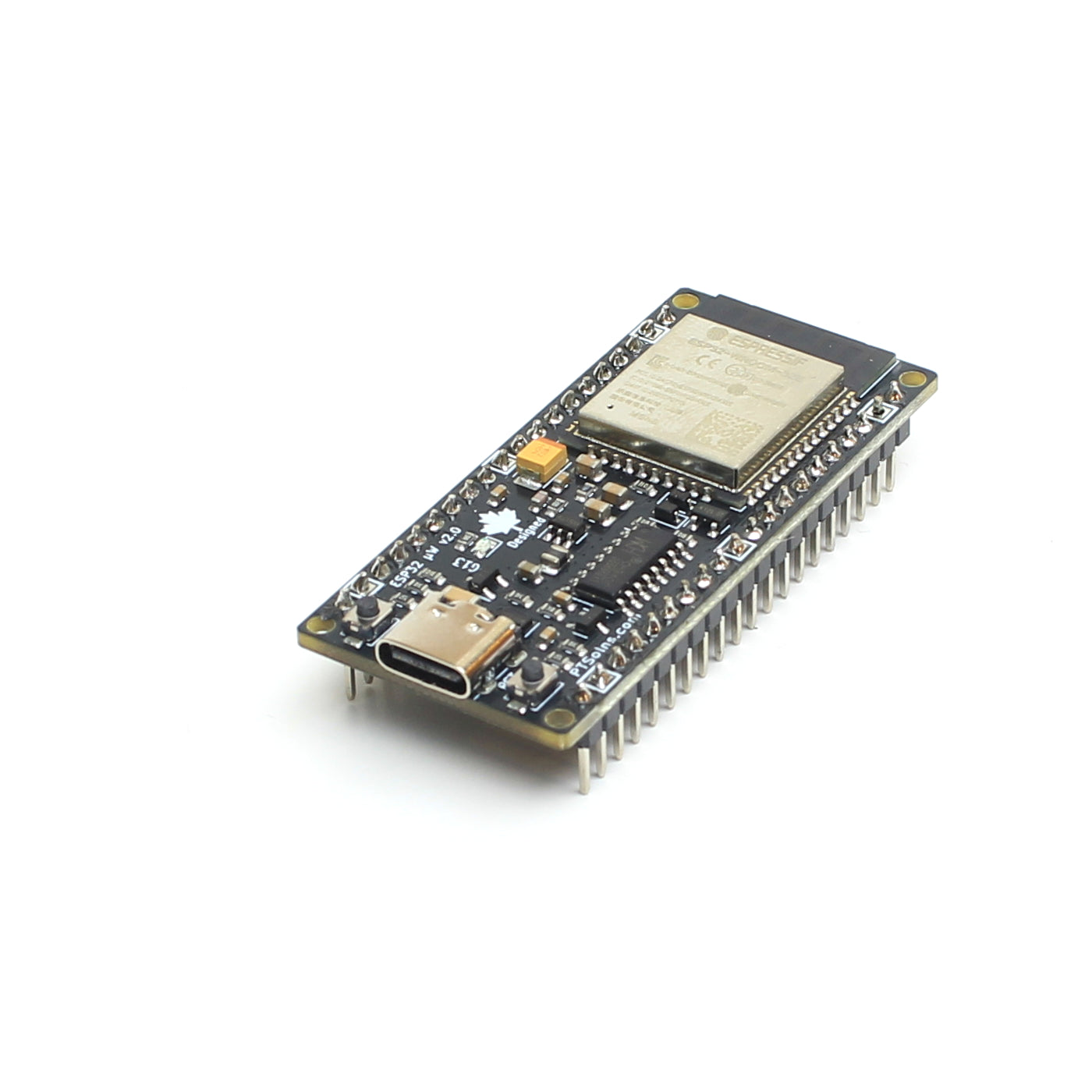
Example: Using the ADS1115 with the Nano Flip Microcontroller
The Nano Flip microcontroller is a compact board that supports 3.3 V logic levels and runs with the Arduino ecosystem. When interfacing it with the ADS1115, make sure both the logic voltage and the I²C lines (SCL/SDA) match. The ADS1115 operates from 2.0 V to 5.5 V, so powering it from 3.3 V is safe and compatible.
Wiring Connections
| ADS1115 Pin | Nano Flip Pin |
|---|---|
| VDD | 5V |
| GND | GND |
| SDA | A4 |
| SCL | A5 |
| ADDR | GND (default I²C address 0x48) |
Arduino Sketch Example
Install the Adafruit ADS1X15 library from the Arduino Library Manager. Upload the following sketch to the Nano Flip.
// Example on ADS1115
// Last update: June 9, 2025
//
// DESCRIPTION
// This example connects the ADS1115 to the PTSolns Nano Flip
//
// There are several gains to set. See below
// There are four channels to set. See below
// Set the delay between readings
//
// Default sets Channel 0 as being read. Take a wire and plug it CH0 pin.
// Then plug it into GND, 3.3V and 5V on the Nano Flip. Observe the reading.
// It should read close to the expect voltages.

#include <wire.h>
#include <adafruit_ads1x15.h>

Adafruit_ADS1115 ads;

// USER SETTINGS
// Options: GAIN_TWOTHIRDS, GAIN_ONE, GAIN_TWO, GAIN_FOUR, GAIN_EIGHT, GAIN_SIXTEEN
adsGain_t ADS_GAIN = GAIN_TWOTHIRDS;
uint8_t ADC_CHANNEL  = 0;  // 0 to 3 for single-ended channels
unsigned long SAMPLE_INTERVAL_MS = 1000;  // Delay between readings (ms)

// Internal map of gain to full-scale voltage range
float getFSR(adsGain_t gain) {
  switch (gain) {
    case GAIN_TWOTHIRDS: return 6.144;
    case GAIN_ONE:       return 4.096;
    case GAIN_TWO:       return 2.048;
    case GAIN_FOUR:      return 1.024;
    case GAIN_EIGHT:     return 0.512;
    case GAIN_SIXTEEN:   return 0.256;
    default:             return 4.096;  // Fallback
  }
}

void setup() {
  Serial.begin(9600);
  ads.setGain(ADS_GAIN);

  if (!ads.begin()) {
    Serial.println("ADS1115 not found. Check wiring.");
    while (1);
  }

  Serial.print("ADS1115 initialized with gain setting: ");
  Serial.println(ADS_GAIN);
  Serial.print("Input voltage range: ±");
  Serial.print(getFSR(ADS_GAIN), 3);
  Serial.println(" V");
}

void loop() {
  int16_t raw = ads.readADC_SingleEnded(ADC_CHANNEL);
  float fsr = getFSR(ADS_GAIN);
  float voltage = raw * fsr / 32767.0;

  Serial.print("AIN");
  Serial.print(ADC_CHANNEL);
  Serial.print(": ");
  Serial.print(raw);
  Serial.print(" -> ");
  Serial.print(voltage, 6);
  Serial.println(" V");

  delay(SAMPLE_INTERVAL_MS);
}
Applications
- Precision sensor measurement (e.g., temperature, pressure, current)
- Data acquisition systems
- Battery monitoring
- Portable or low-power sensing platforms
The ADS1115 offers a powerful yet simple solution to add high-resolution analog sensing to your microcontroller projects. Its I²C interface and small form factor make it easy to integrate even into the tightest of designs.
Verifying the 16-Bit Resolution Manually
To manually verify that the ADS1115 provides true 16-bit resolution, you can perform a simple test by applying a stable, precise input voltage and observing the smallest measurable voltage step it can detect. Since the ADS1115 outputs values as signed 16-bit integers (ranging from –32768 to +32767), the effective resolution is 16 bits. For a given gain setting, each step corresponds to a specific voltage increment, known as the Least Significant Bit (LSB) size. For example, at a ±4.096 V range (GAIN_ONE), each LSB equals about 125 microvolts. By slowly adjusting your input voltage (using a precision voltage source or a fine voltage divider) and reading the raw ADC output, you should observe the output change by increments of 1 count for voltage changes near the LSB size. The ability to resolve these tiny voltage steps confirms the 16-bit resolution.
In contrast, lower-resolution ADCs—such as 12-bit or 10-bit devices—have much larger voltage steps (LSB sizes). For instance, a 12-bit ADC with a ±4.096 V range has about 1 mV per step, eight times coarser than a 16-bit ADC. If you repeat the same voltage adjustment test on a lower-resolution ADC, you will notice fewer discrete output levels and larger voltage increments per count. Thus, by comparing the minimum detectable voltage increment between devices or setups, you can practically verify that the ADS1115 achieves 16-bit resolution while lower-resolution ADCs cannot detect such fine changes.
Package Contents
- 1pcs ADS1115 Module
- 1pcs male header (soldering required)