


I2Connect Quick Connect I2C Module (AHT20)
I2Connect Quick Connect I2C Module (AHT20)
Couldn't load pickup availability
NOTE: For large quantity orders of the I2Connect: AHT20 with custom pricing please contact us directly.
This product has a datasheet!
This product has a 3D model!
This product has a custom library!
Join our Reddit sub r/PTSolns to ask questions, get help from the community, share your projects, and inspire fellow makers with your creations.
Also available on
About this item
- I2Connect Ecosystem: The I2Connect: AHT20 module is designed to seamlessly integrate with the family of I2Connect expansion modules and compatible boards. Using the standardized I2Connect interface (Qwiic®), modules can be connected quickly without soldering, making it easy to add environmental sensing capabilities to new or existing projects. Whether used for education, prototyping, product development, or data logging applications, the I2Connect ecosystem provides a simple and scalable way to expand system functionality.
- Plug & Play Ready: The I2Connect: AHT20 arrives fully assembled and ready to use with no soldering required. Simply connect the module to a compatible I2Connect host board and begin measuring temperature and humidity within minutes. Example code, library support, wiring information, and additional documentation are available in the datasheet.
- Environmental Monitoring: The I2Connect: AHT20 features the AHT20 digital sensor, providing temperature and relative humidity measurements through a simple I2C interface. The sensor is factory calibrated and combines both measurements into a single compact module, making it ideal for environmental monitoring, indoor climate sensing, weather stations, IoT devices, and data logging applications.
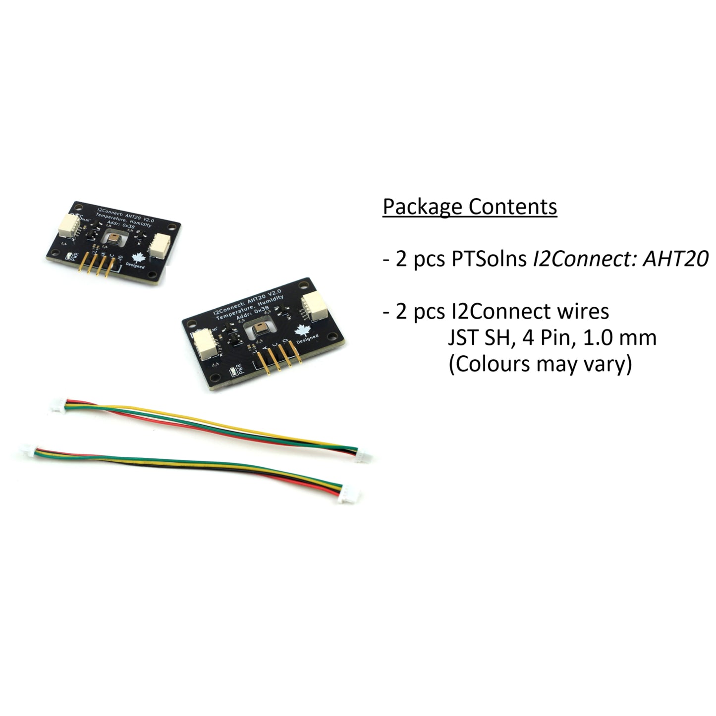
- What’s Included: Each package includes two (2) PTSolns I2Connet: AHT20 boards, fully assembled and two (2) I2Connect (Qwiic®) cables.
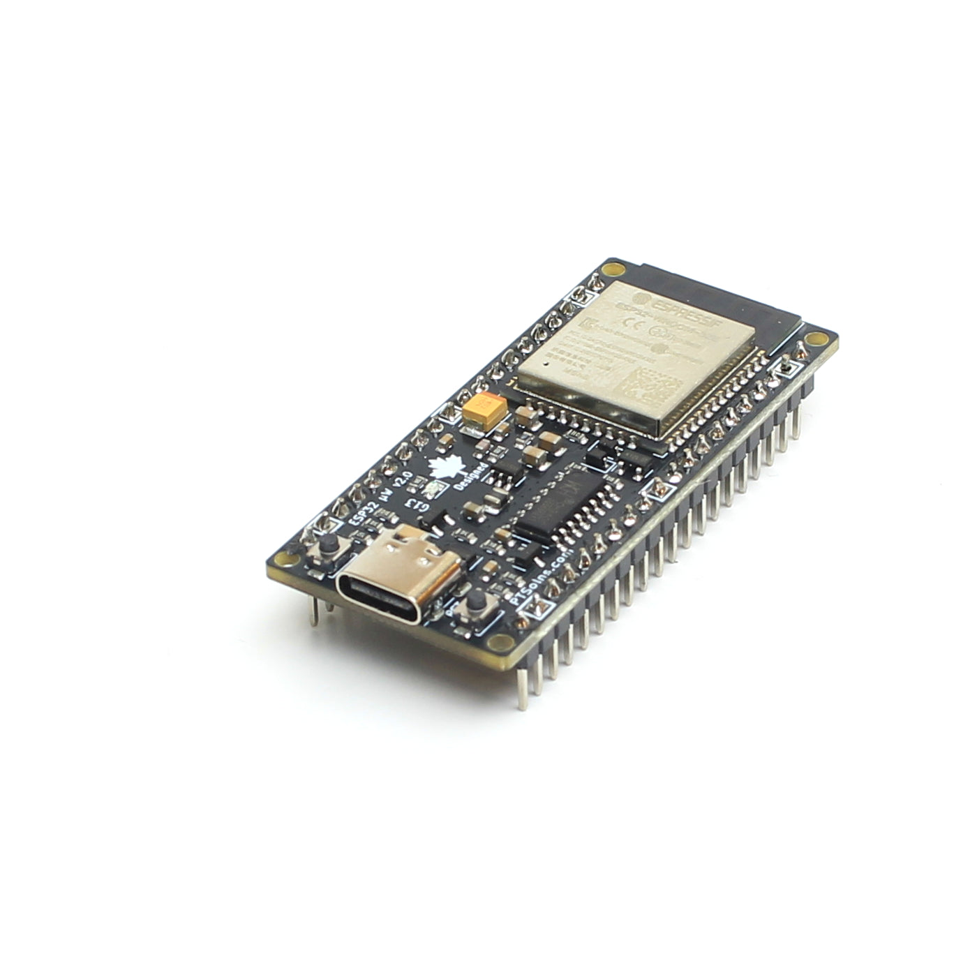
- PTSolns IDE: Use the PTSolns IDE desktop application to program this, and many other, microcontroller development boards. Free to download, many example sketches, 8500+ 3rd party libraries, built in CH340 support.
- PTSolns Customer Support & Resources: We’re here to help. Contact PTSolns support for assistance or technical questions. Every PTSolns product is backed by our comprehensive resource library, including datasheets, schematics, 3D models, Fritzing files, and tutorials. All supporting material is freely available on our PTSolns Documentation Repository.


Product Description
Table of Contents
- I2Connect Series
- What is I2C?
- Technical Features Diagram
- I2C Address
- Wired Connection
- Breadboard Connection
- Compatibility
- Programming & Custom Library
- Mark of Authenticity
- What's Included
- Other Names
The PTSolns I2Connect: AHT20 is a compact temperature and humidity sensing module based on the AHT20 digital sensor. Designed as part of the I2Connect Series, the module provides a simple and reliable way to add environmental sensing capabilities to embedded systems. The sensor communicates over the industry standard I2C interface and delivers temperature and relative humidity measurements with minimal software overhead.
Like all I2Connect modules, the I2Connect: AHT20 is fully assembled and ready to use out of the box. Dual Qwiic® compatible connectors allow the module to be easily integrated into existing I2C systems without soldering, while the preinstalled right-angle header provides direct access to the I2C bus for breadboard-based prototyping. The module is compatible with both 3.3V and 5V systems, making it suitable for use with a wide range of popular microcontroller platforms.
The I2Connect: AHT20 is intended for hobby and educational applications where temperature and humidity monitoring is required. Typical applications include weather stations, environmental monitoring systems, indoor air quality projects, smart home devices, and general-purpose data acquisition systems. Comprehensive documentation, example programs, and dedicated software libraries are provided to help users quickly integrate the module into their projects.
I2Connect Series
The PTSolns I2Connect Series is a family of plug and play expansion modules designed to simplify the integration of sensors, displays, user interfaces, and other peripherals into embedded systems. Built around the industry standard I2C communication protocol and featuring convenient Qwiic® compatible connectors (4 pin, 1 mm JST SH), I2Connect modules can be quickly connected without soldering or complex wiring.
Each module is fully assembled and includes a preinstalled male header that is compatible with standard solderless breadboards, enabling immediate use and rapid prototyping. Designed to work seamlessly with a wide range of microcontroller platforms, I2Connect modules combine compact hardware, comprehensive documentation, and easy to use software libraries. The I2Connect Series enables makers, students, educators, and professionals to rapidly prototype, evaluate, and develop reliable electronic systems.
The following modules are part of the I2Connect Series:
- AHT20: Temperature & Humidity (this product page)
- VEML7700: Light & Lux
- EEPROM: 2Mbit Memory
- Buttons: User Input via 4x4 Matrix of Buttons
- Digit Display: 2x 7-Segment Displays
- ICP-20100: Pressure & Temperature
- KXTJ3-1057: 3-Axies Accelerometer
- MUX: 4-Channel I2C Multiplexer
- OLED: 0.96” 128x64 OLED Display
- I2C Doctor: Improve I2C Bus
What is I2C?
Inter Integrated Circuit, commonly abbreviated as I2C (or I²C, IIC), is a synchronous serial communication protocol widely used throughout the electronics industry for interfacing microcontrollers with peripheral devices such as sensors, displays, memory devices, real time clocks, and input/output expanders. The protocol utilizes two communication signals, Serial Data (SDA) and Serial Clock (SCL), in addition to power and ground, enabling multiple devices to communicate over a common bus architecture while minimizing wiring complexity.
Each device connected to an I2C bus is assigned a unique address, typically a 7 bit address. This addressing scheme allows a single bus master, generally a microcontroller, to selectively communicate with individual devices on the shared bus. Standard 7 bit I2C addressing provides up to 112 usable device addresses, permitting a large number of peripherals to coexist on a single communication interface. In applications requiring additional devices, bus multiplexers can be employed to further expand system capacity.
The I2C specification defines several operating speeds, including Standard Mode (100 kHz), Fast Mode (400 kHz), and Fast Mode Plus (1 MHz). Support for these modes varies by device and application. While I2C was originally intended for communication between devices located on the same printed circuit board, it is commonly used for short cable connections between modules and development boards. Practical cable lengths depend on bus speed, pull up resistor values, wiring quality, and overall bus capacitance. In most embedded applications, cable lengths ranging from a few centimeters to approximately one meter can be achieved reliably, with shorter cable lengths generally permitting higher communication speeds.
The combination of a simple two wire interface, multi device capability, and widespread industry adoption has established I2C as one of the most commonly implemented communication protocols in embedded systems. As a result, I2C is natively supported by the vast majority of modern microcontrollers, development platforms, and peripheral devices.
The oscilloscope capture in Figure 1 shows a typical I2C communication transaction operating at a clock frequency of 100 kHz. The upper trace (purple) represents the SDA (Serial Data) signal, while the lower trace (yellow) represents the SCL (Serial Clock) signal. During communication, the bus master generates the clock pulses on the SCL line, and data is transferred on the SDA line one bit at a time. In accordance with the I2C specification, the state of the SDA signal remains stable while SCL is high and is permitted to change only when SCL is low. Each clock pulse corresponds to the transfer of a single data bit, allowing addresses, commands, and measurement data to be exchanged between the microcontroller and peripheral device. This two wire communication method enables reliable data transfer while maintaining a simple and efficient electrical interface.

[Figure 1: Oscilloscope capture of a typical SDA (top) and SCL (bottom) signal]
Technical Features Diagram
The I2Connect: AHT20 has several technical features depicted in Figure 2.

[Figure 2: Technical Features Diagram for the I2Connect: AHT20]
I2C Address
The I2Connect: AHT20 module uses a fixed I2C address of:
0x38
This address cannot be modified. If multiple AHT20 modules are required in the same system, an I2C multiplexer must be used. The PTSolns I2Connect: MUX module provides four independent I2C channels, allowing up to four AHT20 modules with the same fixed I2C address to be connected to a single microcontroller.
Wired Connection
The most common method of connecting the I2Connect: AHT20 to a microcontroller is through the two onboard Qwiic® compatible connectors (4 pin, 1 mm JST SH). These connectors provide access to the I2C bus and allow modules to be easily connected without soldering. Both connectors are electrically identical, enabling multiple I2Connect modules to be daisy chained together using standard Qwiic® compatible cables. An example of three different I2Connect modules daisy-chained together is shown in Figure 3.

[Figure 3: Daisy-Chain of different I2Connect modules.]
Breadboard Connection
All I2Connect modules are designed to be breadboard friendly and include a preinstalled right angle male header. At a minimum, the I2C interface pins are made available through this header, allowing the module to be easily connected to a microcontroller or prototype circuit using a standard solderless breadboard. Where applicable, additional pins are also exposed to provide access to device specific features and functionality. Right angle headers are intentionally used so that modules stand upright when inserted into a breadboard, improving visibility, accessibility, and user interaction during development, testing, and demonstration.
Figure 4 shows two different I2Connect modules connected to a standard solderless breadboard. The modules are daisy chained together through the exposed I2C pins on the preassembled right angle male headers, allowing both devices to share the same I2C bus.

[Figure 4: I2Connect modules plugged into standard breadboard.]
Compatibility
All I2Connect modules are designed to operate with both 3.3V and 5V microcontroller systems. This flexibility allows the modules to be used with a wide range of popular development platforms without requiring additional level shifting hardware. Modules that support both operating voltages are identified by the “3.3/5V Rated” marking shown in Figure 5.

[Figure 5: The "3.3/5V Rated" compatibility marking found on all I2Connect modules.]
The I2Connect Series utilizes a 4 pin JST SH connector with a 1.0 mm pitch, following the industry standard Qwiic® pinout. The four connections consist of GND, VCC, SDA, and SCL, providing power and I2C communication through a single compact connector. By adhering to the Qwiic® standard connector and pin ordering, I2Connect modules are electrically compatible with a wide range of Qwiic® and STEMMA QT based devices. Additionally, each module includes a preinstalled angled male header that exposes the same signals, allowing the module to be connected directly to virtually any 3.3V or 5V microcontroller system that supports I2C communication, even if a Qwiic® compatible connector is not available.
Programming & Custom Library
The I2Connect Series is designed to integrate seamlessly with all PTSolns microcontroller development boards. Depending on the specific microcontroller, modules can be connected either through onboard Qwiic® compatible connectors or directly through the exposed I2C pins. Since I2C is a widely supported communication standard, I2Connect modules can also be used with many third-party development platforms and microcontrollers.
The choice of development environment is entirely up to the user. PTSolns microcontrollers can be programmed using the PTSolns IDE, the Arduino IDE, and many other compatible development tools. As long as the selected environment supports the target microcontroller and provides access to the I2C peripheral, it can generally be used with I2Connect modules.
To simplify development, the I2Connect: AHT20 module is supported by a dedicated software library. This library provides an easy-to-use interface for configuring the sensor and reading temperature and humidity measurements. The library can be downloaded directly from GitHub (https://github.com/PTSolns/I2Connect_AHT20) or installed through the Library Manager available in both the PTSolns IDE and Arduino IDE by searching for:
I2Connect_AHT20
Example programs are included with the library and demonstrate common tasks such as device initialization, sensor detection, and reading temperature and humidity data. Users are encouraged to review these examples as a starting point for integrating the I2Connect: AHT20 module into their own applications.
Mark of Authenticity
Authentic PTSolns PCBs have a black solder mask color and are marked with the “PTSolns” logo in white silkscreen printing. The “Canadian Designed” symbol, consisting of the Canadian Maple Leaf with the word “Designed” underneath, can also be found on the PCB in white silkscreen printing. The “PTSolns” trademark and the “Canadian Designed” symbols are shown in Figure 6.

[Figure 6: The "Canadian Designed" symbol and the "PTSolns" trademark found on authentic PTSolns PCBs.]
What's Included
- 2x PTSolns I2Connect: AHT20 boards, fully assembled
- 2x I2Connect (Qwiic®) cables
Other Names
-
I2Connect: AHT20
- PTS-00219-201