


Leonardo+ Microcontroller Board - ATmega32U4 Development
Leonardo+ Microcontroller Board - ATmega32U4 Development
Couldn't load pickup availability
NOTE: For large quantity orders of the Leonardo+ Microcontroller Board with custom pricing please contact us directly.
This product has a datasheet!
This product has a 3D model!
This product has example sketches!
This product has a Fritzing model!
This product has a 3D print accessory!
Join our Reddit sub r/PTSolns to ask questions, get help from the community, share your projects, and inspire fellow makers with your creations.
Also available on
- Digikey (180+ countries)
- RobotShop (180+ countries) ... Coming soon
- Amazon (Canada)
About Leonardo+ Microcontroller Board:
- A Classic, Reimagined: PTSolns Leonardo+ (the “Plus” version) microcontroller development board, based on the Microchip ATmega32U4, is a modern twist on a widely popular board. With the same footprint as the Uno form factor, the Leonardo+ remains fully stackable and compatible with many common shields, giving users access to countless features and applications. The Leonardo+ is ideal for STEM education, hobby and home projects, and rapid prototyping, whether you're building custom keyboards or mice, reading sensor data, or interfacing with I2C/SPI buses or RF modules.
- Plug & Play Ready: The Leonardo+ microcontroller development board arrives fully assembled with soldered headers and comes preloaded with an out-of-the-box ready set of test sketches that allow the board to be verified and used immediately. Simply power the Leonardo+ and begin experimenting. These tests include LED patterns, an I2C scanner, PWM output examples, and analog input demonstrations. A description of the tests and additional documentation is available in the datasheet on our PTSolns Documentation Repository.
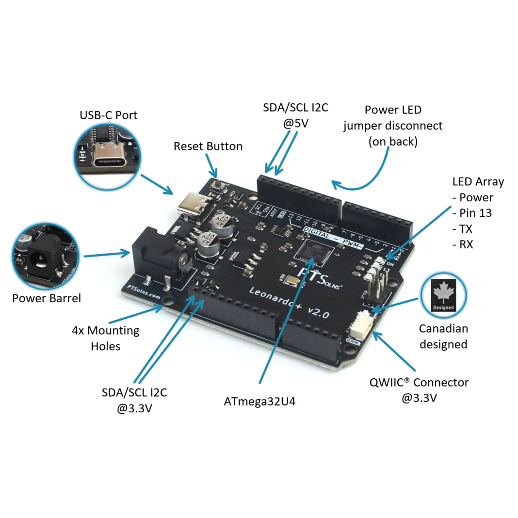
- Packed with Features: The Leonardo+ microcontroller features a modern USB-C port, reset button, grouped status LEDs (Power, Pin 13, TX, and RX), and multiple power input options including USB-C, barrel jack, or VIN. The board provides both a standard 5V I2C bus and a logic-level-shifted 3.3V I2C bus along with a Qwiic connector, making it easy to connect a wide range of sensors and modules without external level shifting. For a complete list of features, pinout details, and electrical ratings, please refer to the datasheet.
- What’s Included: Each package includes one (1) PTSolns Leonardo+ board, fully assembled and individually QC quality checked. USB cable not included. Use a USB-C cable that supports data transfer, as some cables only provide power.
- PTSolns IDE: Use the PTSolns IDE desktop application to program this, and many other, microcontroller development boards. Free to download, many example sketches, 8500+ 3rd party libraries, built in CH340 support.
- PTSolns Customer Support & Resources: We’re here to help. Contact PTSolns support for assistance or technical questions. Every PTSolns product is backed by our comprehensive resource library, including datasheets, schematics, 3D models, Fritzing files, and tutorials. All supporting material is freely available on our PTSolns Documentation Repository.


Product Description

The PTSolns Leonardo+ based on the ATmega32U4, is a popular microcontroller development board with additional unique features. The Leonardo+ has the same footprint as the Uno and continues to be compatible with a range of shields. The board has two extra female header pins that supply SDA and SCL that are shifted from the onboard logic level of 5 V down to 3.3 V. Along with the onboard QWIIC connector, this shifted 3.3 V I2C bus makes it convenient to connect many common sensors and modules that operate on 3.3 V logic No need for extra external components, all the logic level shifting between 5 V and 3.3 V on the I2C bus is done automatically onboard.
The Leonardo+ has a modern USB-C port, and the standard power barrel jack onboard. The board has a new layout of components, such as for example, the grouping of the four LEDs (Power LED, Pin 13 controlled LED, TX and RX communication LEDs). Furthermore, the Leonardo+ allows for a larger current draw on the 3.3 V pin with a rated maximum of 0.8A. This lets the user manage their project’s power budget more easily by allowing a larger current draw.
This version of the Leonardo+ contains the ATmega32U4 IC, perfect for fun projects such as making custom keyboards and mice for computers, among others.
The Leonardo+ comes with a pre-installed out-of-the-box ready set of tests. This gets simple projects started quickly and allows for testing the proper function of the board. A large active online community supports this microcontroller and its programming using the PTSolns IDE software. Many tutorials, projects, schematics, and sketches can be easily found online in blogs, forums and the like. This Plus version offers all of the features users come to learn and expect and adds additional ones that make this board stand out.
This Plus version offers all of the features users come to learn and expect, and adds additional ones that make this board stand out.
All Leonardo+ boards are individually inspected and marked with a quality control sticker (either on the PCB, or on the packaging).
This product, along with all of the PTSolns products, comes with a detailed datasheet, and other supporting material. Please view our PTSolns Documentation Repository to access these documents.
Features of the Leonardo+ Microcontroller Development Board

The following are highlights of the Leonardo+ Microcontroller Development Board. For full details please see the datasheet.
- USB-C Port.
- Reset Button.
- Pinout of I2C bus (SDA/SCL) at 5V logic.
- Power LED jumper disconnect on the back.
- LED array: Power, Pin 13, TX, RX.
- Canadian designed!
- QWIIC connect for I2C bus (SDA/SCL) at 3.3V logic.
- Genuine ATmega32U4 IC.
- Pinout of I2C bus (SDA/SCL) at 3.3V logic.
- Four mounting holes.
- Power barrel.
Endless Possible Applications

Add any Uno Shield to the fully stackable Uno R3+. In this example an RTC MicroSD Shield is stacked. The user can also add the Proto-Shield, the NRF-Shield, the Interface-Shield and so many more!
Check out our shields

The Leonardo+ microcontroller development board is part of a compatible family of products. The Uno Shield as shown here, the Proto-Shield, add lots of features to your projects. Simply stack & play. Check out our line of Uno Shields, including:
- Proto-Shield
- NRF-Shield
- Interface-Shield
- RTC MicroSD Shield
- ... and more coming!
Pinout Diagram of the Leonardo+ Microcontroller Development Board

Ready-to-use out-of-the-box ... Fully assembled, bootloader burned, and "GetStarted" sketch uploaded!
The Leonardo+ microcontroller development board comes ready-to-use out-of-the-box. What does that mean exactly?
- Fully assembled: The Leonardo+ is fully assembled with male headers soldered in place. With the modern USB-C Port onboard, getting started is as easy as plugging it in.
- Experiment ready: The Leonardo+ has bootloader burned, and our custom "GetStarted" sketch has been uploaded.
Get tinkering right away with the five tests uploaded in our custom "GetStarted" sketch (NOTE below). These tests include:
- Test 1: Onboard LED (Pin 13) Blink Unique Pattern. Observe a blinking pattern on the onboard LED.
- Test 2: Onboard LED (Pin 13) Blink Reset Pattern. Observe a different short blinking pattern upon pressing RST.
- Test 3: I2C Scanner (Image with the circled "3" above). Connect a peripheral via I2C and automatically scan its address. View the results in Serial Monitor on baud 9600 (See NOTE below).
- Test 4: Pin 9 Fade (Image with the circled "2" above). Connect an external LED and a resistor from Pin 9 to ground and observe the classic "Fade" example.
- Test 5: Analog A0 Read. Connect a wire to the A0 Pin and observe the readout on the Serial Monitor on baud 9600 (See NOTE below).
These tests are explained in detail in the User Manual of the Uno R3+.
Technical Specifications
Input voltage on USB-C 5 VInput voltage on Vin Pin7-12 VCurrent draw on a GPIO20 mAMax current draw on all GPIOs200 mA (IF OPERATING in “Stable” CONDITIONS. See datasheet for important details.)Max current draw on 3.3 V pin800 mA (IF OPERATING in “Stable” CONDITIONS. See datasheet for important details).Max current draw on 5 V pin800 mA (IF OPERATING in “Stable” CONDITIONS. See datasheet for important details).MicrocontrollerATmega32U4, AVR 8 bit CPU, Up to 16 MHz, Flash Memory: 32 KB, SRAM: 2.5 KB, EEPROM: 1 KB, Peripherals I O Pins: 26, ADC Channels: 12, ADC Resolution: 10 bit, PWM Channels: 7, Timers: 4 (2x 8 bit, 2x 16 bit), USART: 1, SPI: 1, I2C: 1, USB: 1Length68.6 mmWidth53.3 mmWeight21 gMaterialLead free HASL-RoHS surface finish, FR-4 baseMounting Holes4x each with 1.651 mm diameter, see mounting holes diagram for spacing.USB-C NOTEPlease use a USB-C cable that can support data transfer. Not all USB-C cables support data transfer, and can only power a device but not program it.
Other Names
- Leonardo+
- Leonardo +
- Leonardo Plus
- PTS-00211-201