Tinker Thoughts Blog
Welcome to the Tinker Thoughts Blog — hands-on projects, practical tutorials, and insightful tips in the maker and electronics space. We dive into a wide range of topics including Internet of Things (IoT), electronics troubleshooting, home automation, rapid prototyping, and RF communication. You’ll also find detailed guides on 3D printing custom enclosures and PCB mounts, as well as experiments in electrical circuits, embedded systems, and other DIY innovations. Whether you're a hobbyist, engineer, or curious tinkerer, you'll find inspiration and technical depth here.

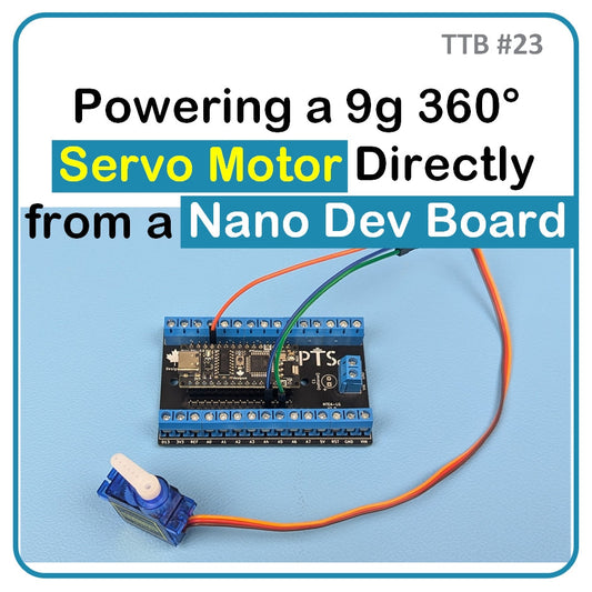
TTB #23: Powering a 9g 360° Servo Motor Directly from a Nano Dev Board
This tutorial investigates whether a 9g 360° servo motor can be powered directly from the Nano Dev Board without external supply. Using detailed current and voltage measurements under start-up, steady-state, and stall conditions, the results show the Nano Flip’s onboard regulator and USB-C path can safely handle the current draw without voltage sag below 4.96 V. Both USB-C and Vin configurations were tested with consistent stability. While this approach is suitable for short tests and educational use, long-term or production designs should still employ a dedicated power supply for servos to ensure reliability and isolation from the microcontroller rail.

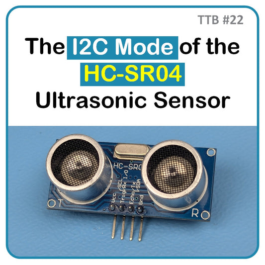
TTB #22: The I2C Mode of the HC-SR04 Ultrasonic Sensor
The HC-SR04 (2021 version) ultrasonic sensor upgrades the classic HC-SR04 by integrating an RCWL-9200 controller, enabling four communication modes: GPIO, I²C, 1-Wire, and UART. This tutorial focuses on the I²C mode, which is enabled by bridging the M1 jumper and leaving M2 open. In this mode, the module communicates over SDA and SCL lines at address 0x57, requiring only two pins on the microcontroller. It delivers precise distance readings from about 2 cm up to 4–5 meters. We cover mode selection, wiring, and a working Arduino sketch to read centimeter values directly from the sensor via the I²C bus.

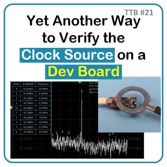
TTB #21: [Guest Post] Yet Another Way to Verify the Clock Source on a Dev Board
Determining the clock source on a microcontroller development board is essential for debugging and validation. Traditional methods like reading crystal markings or setting fuses can be risky or unreliable. In this tutorial, we demonstrate a safer, faster approach using an oscilloscope with FFT capability and near-field sniffer probes. By probing the Nano Flip’s external crystal, the FFT reveals a clear 16 MHz peak, confirming the clock frequency without altering fuses. Beyond verification, these probes are valuable for EMI troubleshooting and pre-compliance testing, helping engineers quickly identify noise sources before formal FCC or ISED certification testing.

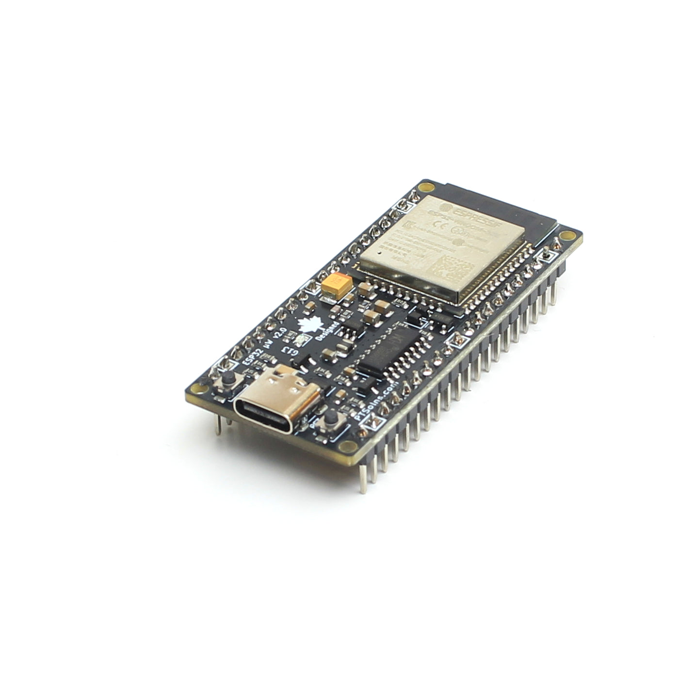
TTB #20: Thermal Response of Microcontrollers During Deep Sleep and Active Modes
Deep sleep is essential for battery-powered microcontroller applications, but what does it really look like in practice? Using a thermal camera, we compared the PTSolns Nano Flip (ATmega328P) and the ESP32 microWatt to visualize their thermal behavior in both deep sleep and active modes. The results show clear differences in power efficiency and thermal response, with the ESP32 microWatt’s design proving ideal for low-power, battery-driven projects. Along the way, we also uncovered how onboard components like the CH340 influence power draw and even how shiny surfaces can mislead thermal imaging. Read on to see the full findings.

TTB #19: Saving a Broken Dev Board with a USB-UART Bridge
When the USB port snaps off your development board, it may feel like game over. But don’t toss it yet. If the board itself is still functional, a USB-UART Bridge can bring it back to life by handling programming and communication with your computer. In this blog, we explore how the U2B adapter works with both 5V and 3.3V boards, including the Nano Flip 3V3, and outline the key wiring steps to get you back on track. Whether fixing a broken board or programming one that never had USB, the U2B is a must-have tool.

TTB #18: [Guest Post] Using EEPROM on the Nano Flip to Make a Button Logger
The Nano Flip, built on the ATmega328P, includes 1 KB of EEPROM memory that retains data even after power loss. This tutorial demonstrates how to use EEPROM in a simple but practical button press logger. Each press increments a counter which is stored permanently in the EEPROM. The current counter value is displayed on an I2C LCD, making it easy to visualize the data. By leveraging EEPROM, your project can survive resets or power outages, continuing exactly where it left off. This same approach can be extended to countless applications and use cases.

