Tinker Thoughts Blog
Welcome to the Tinker Thoughts Blog — hands-on projects, practical tutorials, and insightful tips in the maker and electronics space. We dive into a wide range of topics including Internet of Things (IoT), electronics troubleshooting, home automation, rapid prototyping, and RF communication. You’ll also find detailed guides on 3D printing custom enclosures and PCB mounts, as well as experiments in electrical circuits, embedded systems, and other DIY innovations. Whether you're a hobbyist, engineer, or curious tinkerer, you'll find inspiration and technical depth here.
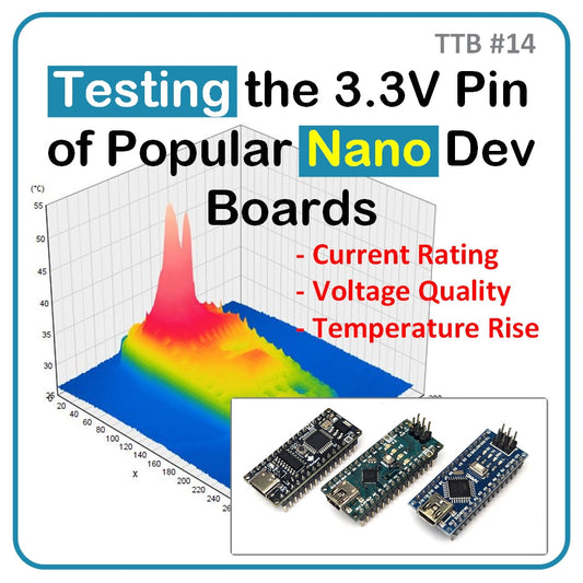
TTB #14: Testing the 3.3V Pin of Popular Nano Dev Boards
In this post, we compare the 3.3V pin performance of three Nano-style development boards under two load conditions: 50 mA and 100 mA. We measure voltage quality and temperature rise using a precise resistive load, oscilloscope, and thermal camera. Each board is scored across five categories, including current rating, voltage quality, and temperature rise. Despite similar pinouts, the boards show major differences in performance. One board stands out with superior voltage regulation, higher current capacity, and lower temperature rise under load, making it the top choice for reliable 3.3V rail applications.
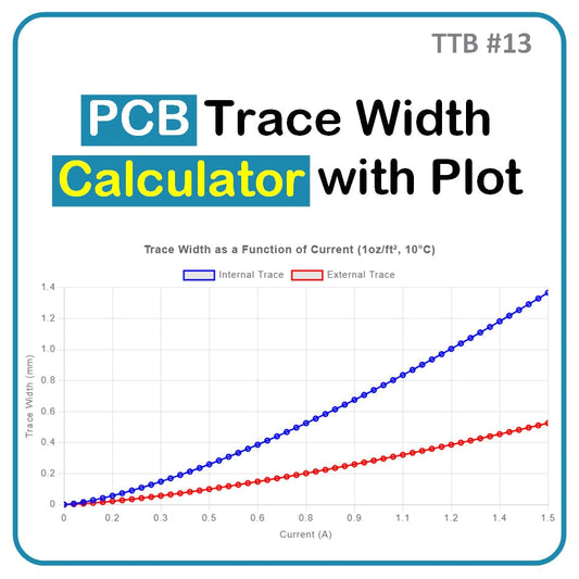
TTB #13: PCB Trace Width Calculator with Plot
The PCB Trace Width Calculator uses IPC-2221 to estimate trace width, resistance, voltage drop, and power loss for internal and external PCB layers. It supports unit selection, graphing, and quick approximations—ideal for early-stage design and educational use.

TTB #12: Non-Compliant Use of CH340 V3 Pin: Deep Dive for Engineers
In this technical deep dive, we examine the CH340 USB-to-serial converter and a curious V3 pin configuration used by SparkFun. While the CH340 datasheet specifies tying V3 to VCC in 3.3V mode, SparkFun connects it only to a capacitor—seemingly a violation. Through bench tests, we found the internal LDO enters dropout mode at 3.3V, allowing V3 to stay near VCC as long as no external current is drawn. This explains why SparkFun’s CH340 design remains reliable. We validate their approach and confirm its safe use in our own CH340C-based products, including our upcoming board.

TTB #11: Introducing PTSolns‑GPT
Today we’re excited to announce PTSolns‑GPT, a powerful new addition to the PTSolns ecosystem. Trained specifically for PTSolns products and related projects. We threw everything at it but the kitchen sink to make it as knowledgeable as possible. Datasheets, custom libraries, tutorials, and everything else!
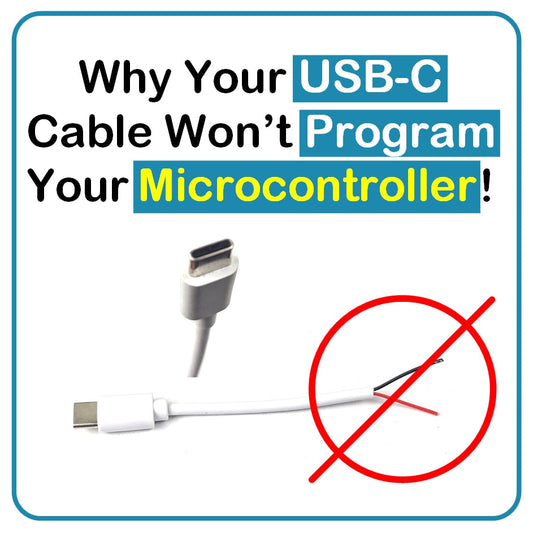
TTB #10: Why Your USB-C Cable Won't Program Your Microcontroller
Think all USB-C cables are the same? Think again. In this video, I demonstrate why some USB-C cables won’t let you upload code to your microcontroller — even though they still charge your device. If you've been struggling to connect to your PTSolns Nano Flip, PTSolns ESP32 microWatt, or any other board and keep getting mysterious errors, your cable might be the problem. Many USB-C cables are power-only and completely lack the data lines required for programming. Watch as we show how to spot the difference, test your cables, and avoid this frustrating mistake in future projects.
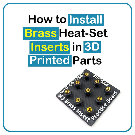
TTB #9: How to Install Brass Heat Set Inserts in 3D Printed Parts
Learn how to install M3 brass heat-set inserts into 3D prints using a reliable and beginner-friendly method. This technique is perfect for securely fastening lids or mounting PCBs inside custom enclosures. In this video, we guide you through the essential tools and walk you through each step to insert the brass nuts cleanly and accurately. Whether you're new to 3D printing or looking to improve your builds, this method provides strong, professional-grade fastening that works for various insert sizes.