


RTC MicroSD Data Logging Shield for Uno (Arduino Compatible)
RTC MicroSD Data Logging Shield for Uno (Arduino Compatible)
Regular price
$19.99 CAD
Regular price
Sale price
$19.99 CAD
Unit price
per
Shipping calculated at checkout.
Couldn't load pickup availability
NOTE: For large quantity orders of the RTC MicroSD Shield with custom pricing please contact us directly.
This product has a datasheet!
This product has a 3D model!
This product has example sketches!
Also available on
-
Digikey (180+ countries)
- Jameco (North America)
- RobotShop (180+ countries)
-
Amazon (Canada)
- Amazon (USA) ... coming soon
About this item
- Packed with Features: The RTC MicroSD Shield is a data logging shield for the Uno microcontroller development board. But this shield does more than data logging … Use it to play back files from the SD card. Use it to connect a QWIIC connector sensor module and quickly gather data. Use it to generate square wave signals. Use it to keep track of time and the date. Use it to store critical data in the EEPROM. Or use it in a stack to gain even more features. This shield is so packed with features we recommend the user to read the datasheet which can be found on our “PTSolns Documentation Repository”.
- Configurability: The RTC MicroSD Shield data logging shield for the Uno microcontroller development board can be configured in many ways. The back of the PCB has many user configurable hardware connections to assign pin definitions as required in your project. This provides more flexibility when stacking other shields that have hardcoded hardware pins occupying a pin that is required elsewhere.
- Compatibility: The RTC MicroSD Shield is compatible with the PTSolns Uno R3+, as well as any other Arduino compatible Uno R3 or R4. The form factor of the shield has the same width as the Uno and matches all of the pinouts. The RTC MicroSD Shield is fully stackable and comes with all the required stacking headers.
- What’s Included: Each package includes one (1) RTC MicroSD Shield, one (1) set of stacking female headers. This is a kit, SOLDERING REQUIRED. SD card and coin battery are NOT included.
- PTSolns Customer Support & Resources: We’re here to help. Contact PTSolns support for assistance or technical questions. Every PTSolns product is backed by our comprehensive resource library, including datasheets, schematics, 3D models, Fritzing files, and tutorials. All supporting material is freely available on our “PTSolns Documentation Repository”.
Product Description

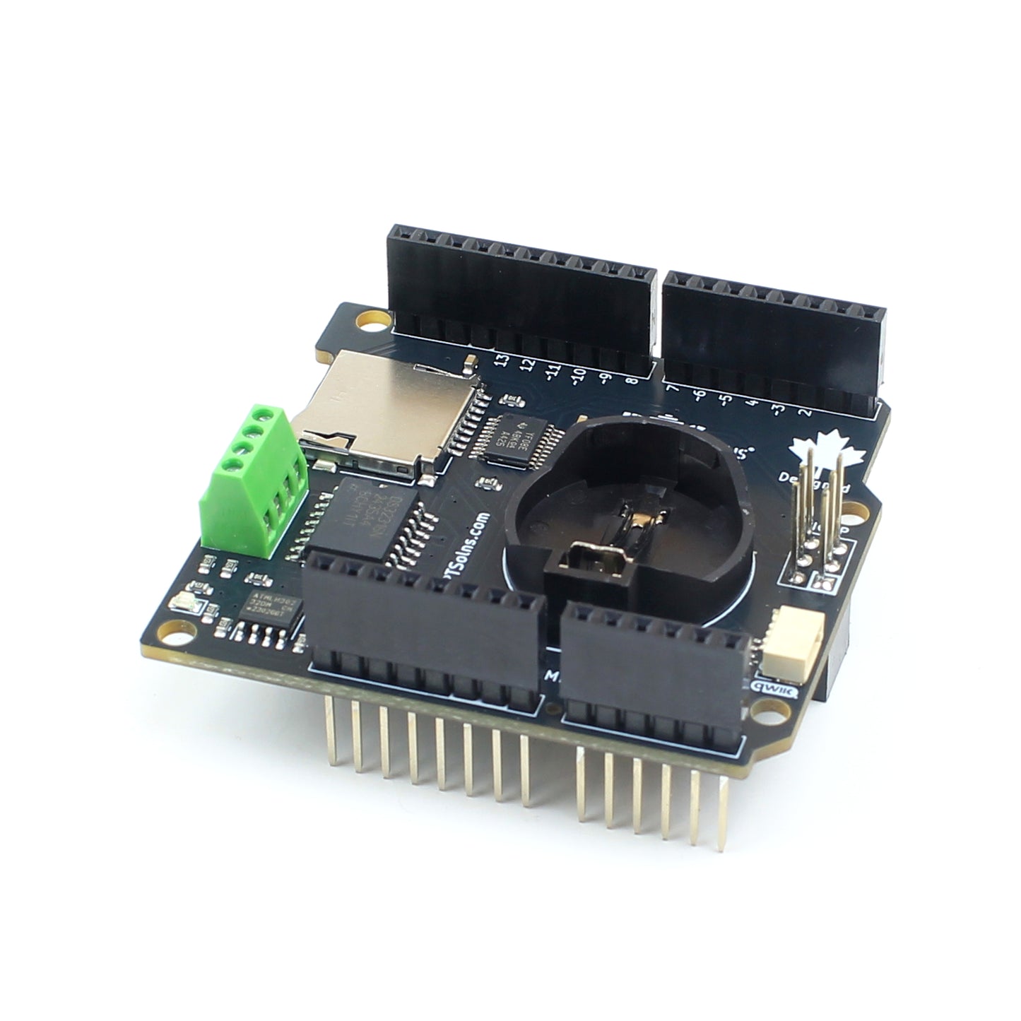
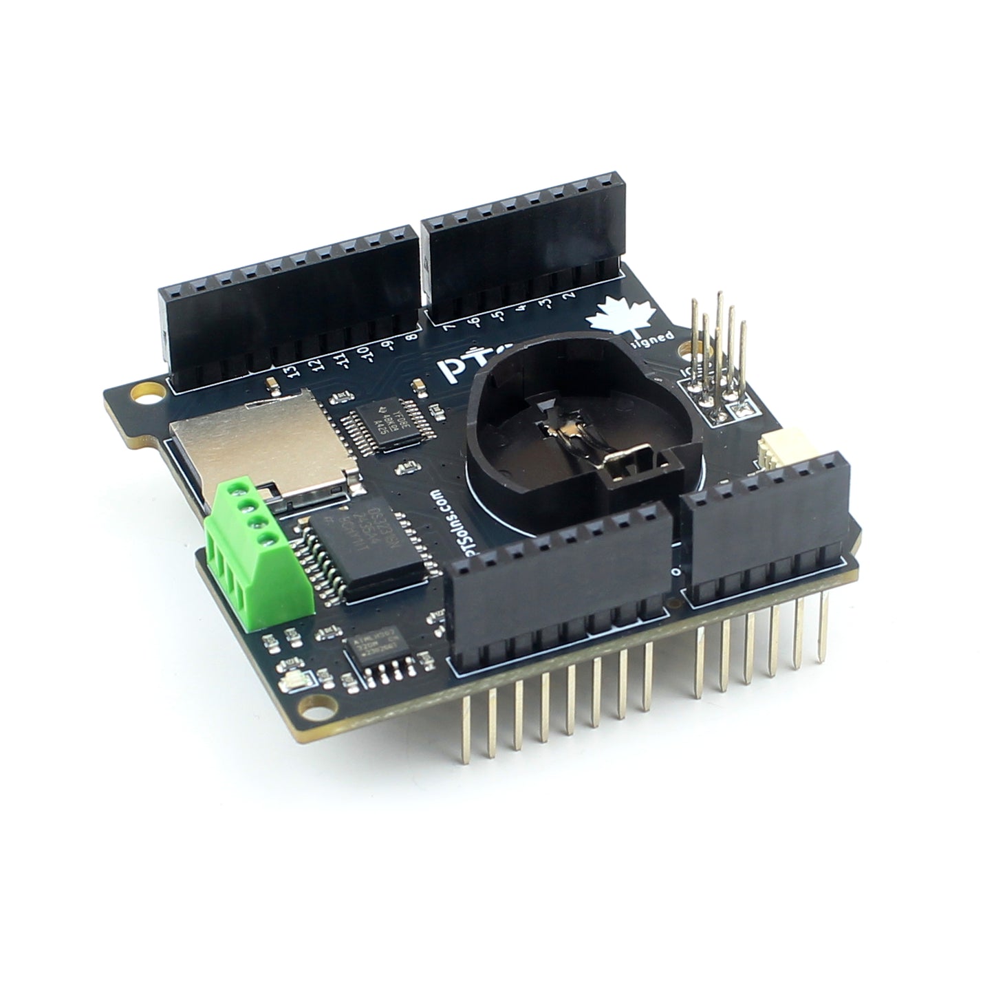
The PTSolns RTC MicroSD Shield is intended for data logging where precise time/date stamps and/or nonvolatile memory are required. The shield is outfitted with a real-time clock (RTC) and optional backup battery, a Micro SD card reader, extra EEPROM, an input/output signal port, and a QWIIC connector.
Several hardware configuration options make this shield very flexible by allowing pin definitions to be changed by the user. The shield is fully stackable and compatible with all the common 5V Uno microcontroller development boards variations.
The RTC MicroSD Shield data logging shield is ideal for quick prototyping, testing, and educational settings. The QWIIC connector allows for many different I2C modules to be added easily and getting a project started quickly. Several fully detailed example sketches are available to showcase all the features of the shield.
This product, along with all of the PTSolns products, comes with a detailed datasheet, and other supporting material. Please view our "PTSolns Documentation Repository" to access these documents.
Shield-Series
This product is part of the Shield-Series. All the members of this series include:
-
Proto-Shield
-
NRF-Shield
- Interface-Shield
- RTC MicroSD Shield (this product page)
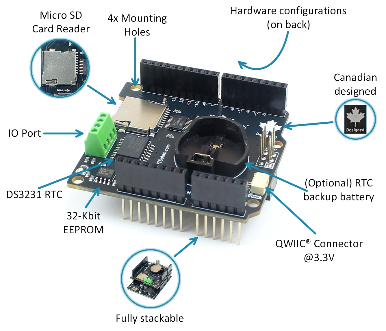
Features of the RTC MicroSD Shield

The following are highlights of the RTC MicroSD Shield. For full details please see the datasheet which can be found in our "PTSolns Documentation Repository".
- Micro SD Card reader (SPI addressable
- DS3231 RTC (I2C addressable)
- (Optional) RTC backup battery
- 32-Kbit EEPROM (I2C addressable)
- Onboard Logic Level Shifter (LLS) to provide I2C bus at 3.3V
- QWIIC connector (I2C bus at 3.3V)
- Several hardware pin configurations (on the back)
- IO Port for various signals
- Fully stackable
- Four mounting holes (same dimensions as the Uno microcontroller development board)
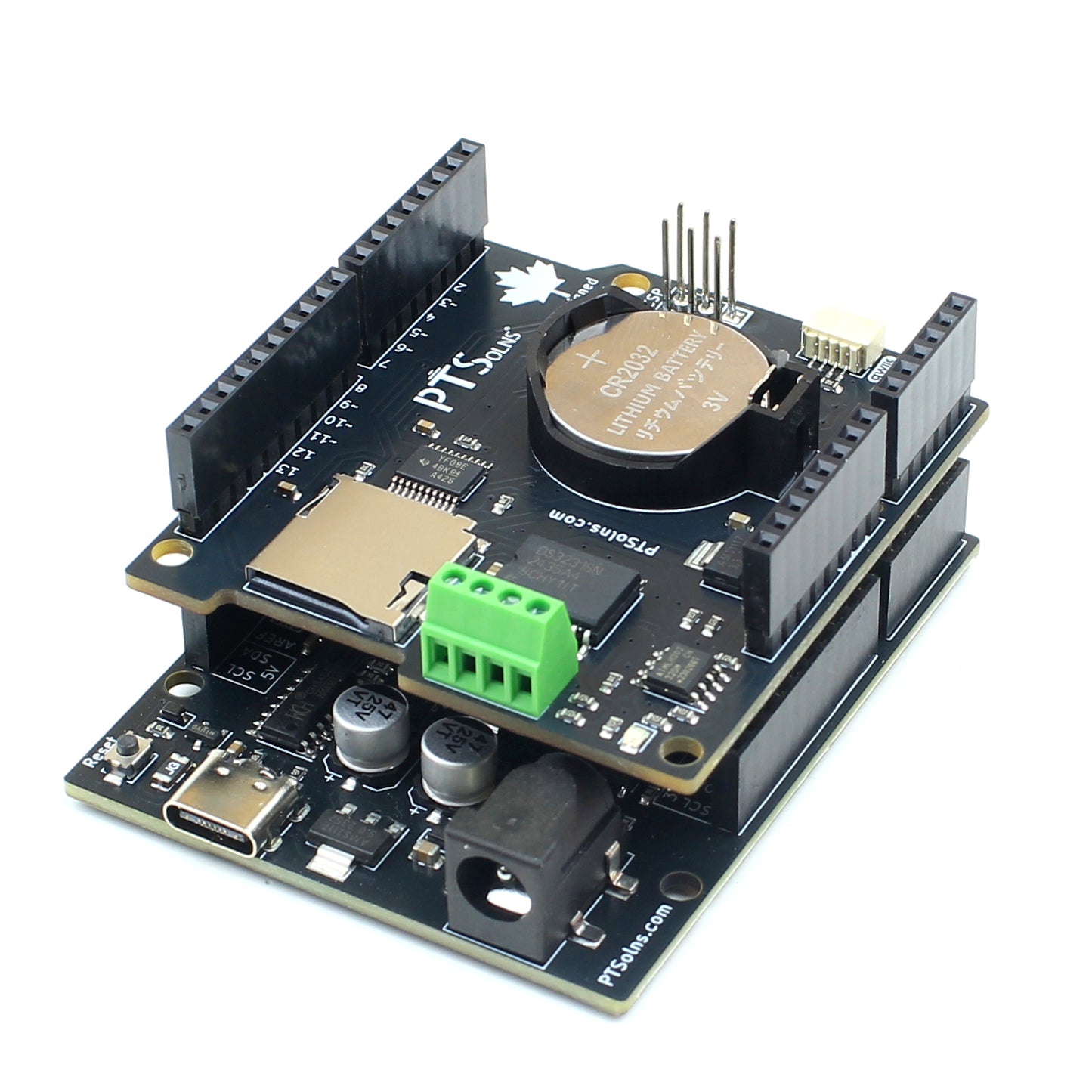
Fully Stackable

Shown in the above image is the RTC MicroSD Shield stacked onto the PTSolns Uno R3+. With a slightly shorter footprint the shield fits well onto the Uno R3+. The Uno data logging shield is compatible with the following boards:
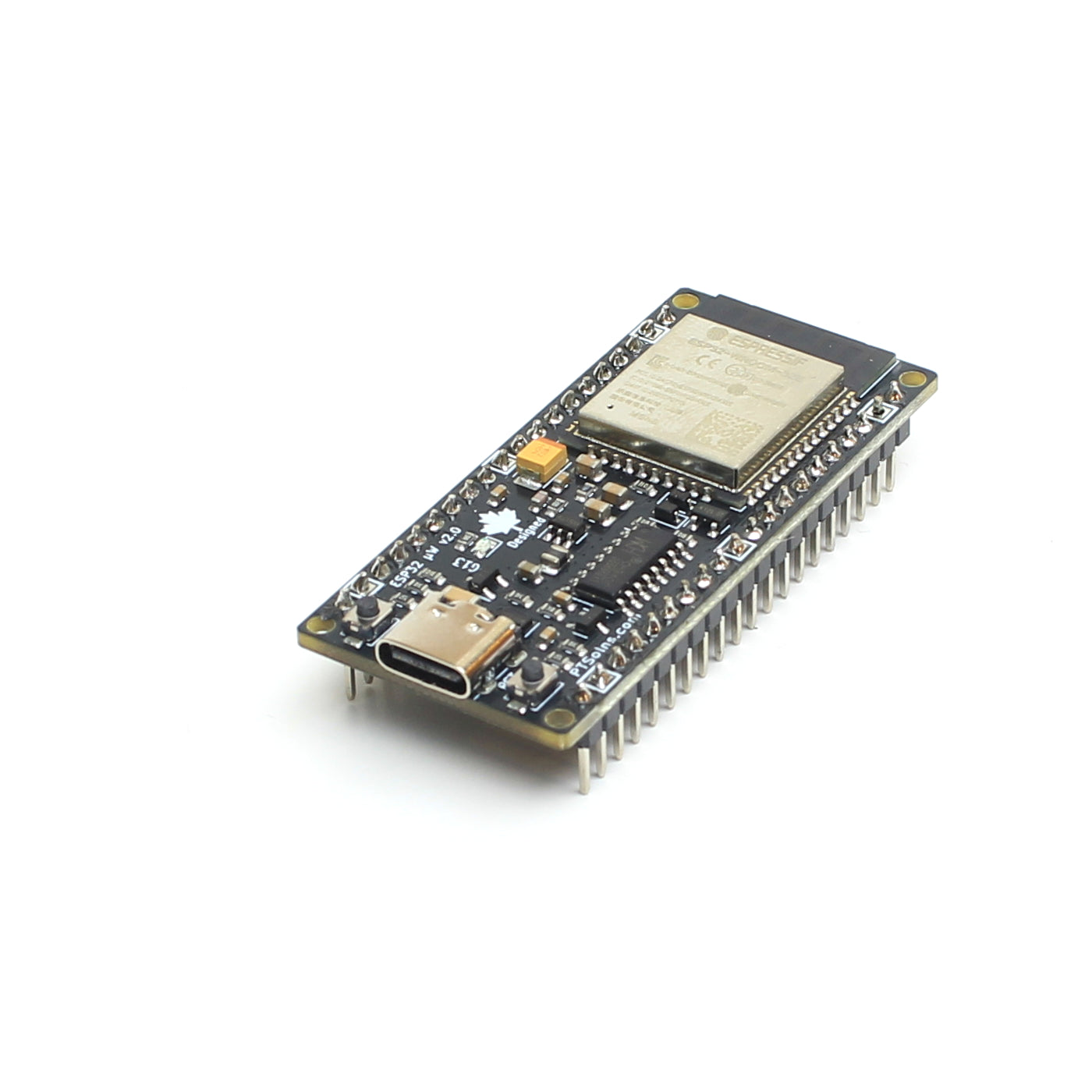
- PTSolns Uno R3+
- PTSolns DIY Uno Kit (coming soon)
- Arduino Uno R2 Wifi
- Arduino Uno R3
- Arduino Uno R4 Wifi
- Arduino Uno R4 Minima
- Arduino Leonardo
- Arduino Mega 2560
- Most generic 5V Uno R3/R4 clone
Endless Applications - Data Logging

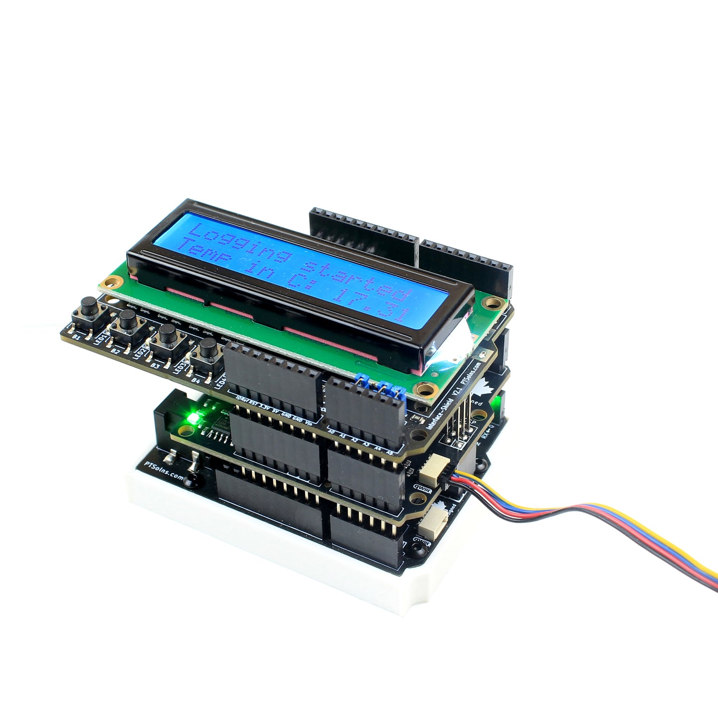
Shown in the above image is the RTC MicroSD Shield stacked onto the PTSolns Uno R3+ with a PTSolns Interface-Shield stacked on top. In the QWIIC connector is a temperature sensor that is gathering data and displaying values on the LCD. The sketch takes a sensor measurement every 10 seconds and saves the results to the Micro SD card to a TXT file.
Usage and Application
To demonstrate the various features and configuration options of the RTC MicroSD Shield, four detailed examples (Arduino IDE sketches) are provided. All associated code can be downloaded from the "PTSolns Documentation Repository", under the subfolder "PTS-00204-211_RTC_MicroSD_Shield" inside the "Sketches" subfolder. These example sketches include:
- Detailed_tests.ino - This sketch is designed to give the user familiarity with the various features of the RTC MicroSD Shield. The following tests can be enabled in this sketch: I2C Scanner Test, RTC Test, EEPROM Test, and SD Card Test. Each of these tests have various options and detailed descriptions. By default, only the first test is enabled. The user is encouraged to go through all the tests to fully understand the various features and software and hardware configurations of the shield.
- RTC_Alarm_Trigger_with_Interrupt.ino - This sketch only uses the RTC onboard the Shield and demonstrates how the RTC can provide an interrupt to the microcontroller. A countdown is started and after 10 seconds, an Alarm (alarm(1)) is triggered which causes an interrupt. During the interrupt the onboard LED flashes for 3 seconds. Then the alarm is cleared, and the cycle is repeated.
- Sensor_Data_Logging.ino - This sketch is to demonstrate how to connect a sensor via the I2C Qwiic connector and record the data to an SD card. This example has the BMP280 sensor connected, however any similar modules can be used. It takes a temperature reading every minute and records it to the SD card.
- SQW_output.ino - This sketch employs the RTC to output a square wave of four hardcoded frequencies: 1 Hz, 1.024 kHz, 4.096 kHz, and 8.192 kHz. The user can change between these four outputs by restarting the microcontroller. Each time the sketch begins an integer is read from the onboard EEPROM, incremented, and saved back to the EEPROM. In this manner the restart button is used as a selection button for the four modes, cycling through the modes with each press. The square wave output (shown in the image above) by the RTC have a peak-to-peak voltage of 5 V. The square wave signal can be connected to an oscilloscope to show the waveform, which is done in Figure 8 for the 4.096 kHz mode.

Other Names
- RTC MicroSD Shield
- Data Logging Shield
- Datalogging Shield
- PTS-00204-111
- PTS-00204-211